Sizing a cordless tool pack from amp-hours alone is the most common mistake in the category. A 3.0 Ah 18 V pack is not a guarantee of a certain runtime, a certain torque or a certain cycle life. The tool's motor efficiency, the actual duty cycle, the pack's internal resistance, the ambient temperature, the end-of-life capacity and the charger's termination all change the answer. This paper sets out a six-step method that starts with the tool and ends with a pack specification a supplier can quote and a test house can verify.
The first step is a load audit, not a catalogue search. The same 18 V interface carries a compact drill, an impact driver, a circular saw and a leaf blower. Their current profiles are different, and the pack must be sized for the worst combination of continuous thermal load and short peak current that the tool can produce.
| Load audit item | What to record | Why it matters |
|---|---|---|
| Tool family and model | Drill, impact driver, saw, grinder, blower, trimmer | Sets the mechanism, motor and typical duty |
| Rated mechanical output | Watts, torque, no-load speed | Converts to DC input through motor efficiency |
| Continuous running current | Measured or calculated at typical load | Sets cell C-rate and thermal design |
| Peak and stall current | Measured with a current probe or from the controller limit | Sets fuse, PTC, connector and switch rating |
| Duty cycle | Trigger-on time versus rest time over a workday | Sets energy and RMS heating |
| Ambient and storage temperature | Indoor, outdoor, vehicle, unheated workshop | Sets capacity derating and charge limits |
| Charge window | Minutes available, charger current, pack cooling | Sets fast-charge capability and cell matching |
A load audit can be as simple as a clamp meter and a stopwatch. Measure the current at no load, at a representative cut, and at stall. Record how long each condition lasts. A pack designed from a catalogue's "18 V 3.0 Ah" label will miss all of this.
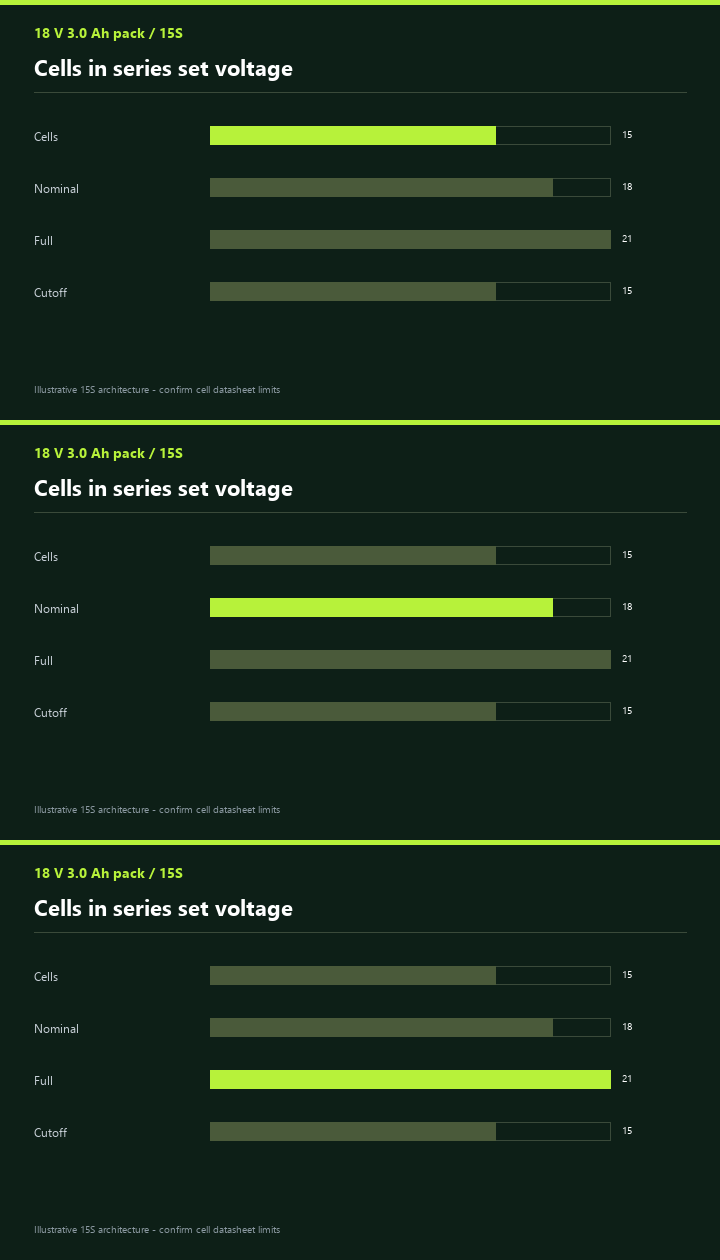
The nominal voltage is the series count multiplied by 1.2 V for NiMH. The full-charge and cutoff voltages follow from the per-cell limits. The table below gives the common architectures; the values are approximate and must be confirmed against the chosen cell datasheet.
| Architecture | Series count | Nominal | Full charge at 1.40–1.45 V/cell | Cutoff at 1.0 V/cell | Typical use |
|---|---|---|---|---|---|
| 12 V | 10S | 12.0 V | 14.0–14.5 V | 10.0 V | Compact drill, driver, detail sander |
| 18 V | 15S | 18.0 V | 21.0–21.75 V | 15.0 V | Main hand-tool platform |
| 24 V | 20S | 24.0 V | 28.0–29.0 V | 20.0 V | Heavy drill, rotary hammer, garden tool |
| 36 V | 30S | 36.0 V | 42.0–43.5 V | 30.0 V | Mower, chainsaw, heavy stationary tool |
The full-charge voltage is the first place a low-cost design fails. A 15S pack at 1.45 V per cell reaches 21.75 V. If the tool's switch or speed controller is rated only for 18 V nominal, it may arc, overheat or fail at the top of the charge. The cutoff is the second place: 1.0 V per cell is a conservative compromise between runtime and cell protection; 0.9 V per cell gains a little runtime but increases the risk of cell reversal in a mismatched string.
NiMH tool packs overwhelmingly use Sub-C (SC) or 4/5 Sub-C cells because they offer a good balance of high-rate capability, capacity and pack size. AA cells can be used in light-duty tools, but their current capability and thermal path are limited. The table below compares typical formats; the capacity and current values are illustrative and vary by supplier.
| Format | Approximate size | Typical capacity | Typical continuous / peak | Best use |
|---|---|---|---|---|
| AA | 14.5 mm × 50.5 mm | 1.2–2.7 Ah | 2–5 A / 10–15 A | Light drivers, LED tools, low-cost 12 V packs |
| 4/5 Sub-C | 23 mm × 34 mm | 1.2–2.0 Ah | 5–10 A / 20–30 A | Compact 12 V and 18 V packs |
| Sub-C | 23 mm × 43 mm | 2.0–3.5 Ah | 10–20 A / 30–60 A | Main 18 V hand tools, saws, grinders |
| High-rate Sub-C | 23 mm × 43 mm | 1.5–3.0 Ah | 15–30 A / 60–80 A | Impact tools, heavy saws, short bursts |
The trade-off is not only capacity. A high-capacity Sub-C cell often has a thicker electrode and higher internal resistance than a high-rate cell of the same size. It stores more energy but sags more under a 30 A load. A high-rate cell stores less but holds voltage better. The pack designer must choose which the tool needs, then verify with a discharge test at the actual pulse profile.
Start with the energy the tool needs at the motor shaft, convert to DC input through motor and controller efficiency, then divide by the usable pack energy. A worked example makes the method concrete. The numbers are illustrative, not a claim about any specific tool.
EDC = Pmech × t / ηmotor+drive and Crequired = EDC / (Vnom × kderate)
| Parameter | Example value | Basis |
|---|---|---|
| Mechanical output | 100 W | Representative compact 18 V drill under medium load |
| Motor and drive efficiency | 75 % | Brushed or brushless motor plus gearbox and controller |
| DC input while running | 133 W | 100 W / 0.75 |
| Current at 18 V | 7.4 A | 133 W / 18 V |
| Trigger-on time for a 3.0 Ah pack | 24.3 min | 3.0 Ah / 7.4 A |
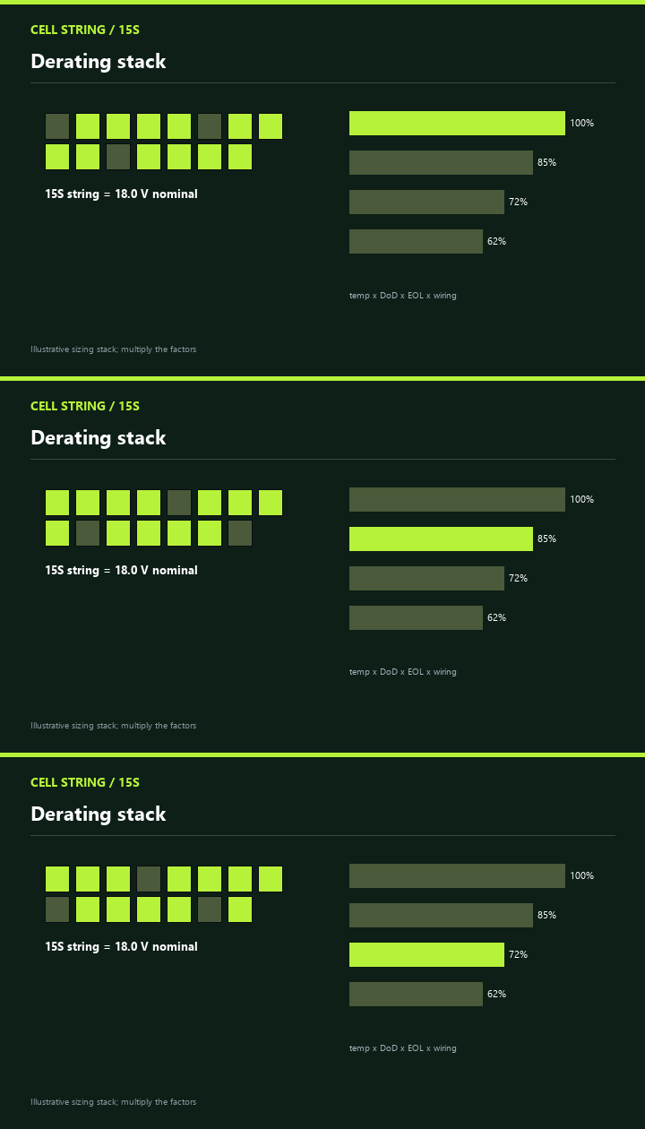
| Derating stack | 0.85 × 0.85 × 0.90 × 0.95 ≈ 0.62 | Temperature, depth of discharge, end of life, wiring |
| Usable energy | ≈ 33.4 Wh | 54 Wh nameplate × 0.62 |
| Realistic trigger-on time | ≈ 15.1 min | 33.4 Wh / 133 W × 60 |
| Elapsed time at 30 % duty | ≈ 50 min | 15.1 min / 0.30 |
The same pack can look adequate or inadequate depending on the duty. At 30 % duty, a 3.0 Ah pack gives about fifty minutes of workday time. At 80 % duty, the same pack gives about nineteen minutes. A tool advertised as "long runtime" is usually quoting a low-duty application, not a continuous grinding or blowing task. The quotation should state the duty.
| Duty cycle | Elapsed runtime from 33.4 Wh usable | What the user experiences |
|---|---|---|
| 20 % | ≈ 75 min | Assembly, intermittent fastening |
| 30 % | ≈ 50 min | Mixed drilling and positioning |
| 50 % | ≈ 30 min | Continuous sawing with breaks |
| 80 % | ≈ 19 min | Grinding, blowing, heavy garden work |
| 100 % | ≈ 15 min | Continuous trigger-on; thermal limit may intervene first |
The derating stack is multiplicative, not additive. A pack that is cold, near end of life, running at high rate and losing voltage in the wiring can lose nearly half its nameplate energy before the tool sees it. The stack also explains why a 4.0 Ah pack does not give 33 % more runtime than a 3.0 Ah pack if its cells have higher internal resistance and the tool is drawing high current.
Capacity is only half the design. The pack must deliver the current without collapsing the voltage below the tool's cutoff or the electronics' reset threshold. The table below uses a 15S pack with 6 mΩ per cell and 90 mΩ total pack resistance, including welds, wiring and connector. The values are illustrative.
| Current | I²R loss in pack | Voltage sag | Terminal voltage from 19.5 V OCV | Design consequence |
|---|---|---|---|---|
| 10 A | 9 W | 0.9 V | 18.6 V | Normal drilling; minor heating |
| 20 A | 36 W | 1.8 V | 17.7 V | Heavy sawing; noticeable speed drop |
| 30 A | 81 W | 2.7 V | 16.8 V | Grinding; thermal design must use RMS current |
| 50 A | 225 W | 4.5 V | 15.0 V | Approaching cutoff; protection may trip |
| 70 A | 441 W | 6.3 V | 13.2 V | Stall; electronics reset or fuse operates |
The connector is part of the resistance. A poor spring contact, a oxidized terminal or a undersized wire can add tens of milliohms. At 30 A, an extra 20 mΩ adds 0.6 V of sag and 18 W of heat at the contact. The pack should be tested at the connector, not only at the cell stack. A thermal camera on the battery terminals after a heavy cut is a useful acceptance test.
NiMH charging is a controlled overcharge process. The charger must deliver enough current to charge in the available window, then terminate reliably. A simple timer is acceptable only when the pack is deeply discharged and the charger current is low; a fast charger needs −ΔV, temperature rise and a backup timer.
| Charge parameter | Typical value | Why it matters |
|---|---|---|
| Standard charge | 0.1 C for 14–16 h | Simple, gentle, but slow; timer must match capacity |
| Fast charge | 0.5–1 C for 1–2 h | Requires −ΔV and temperature cutoff; cell matching critical |
| −ΔV termination | 5–10 mV per cell | Detects the voltage dip at full charge |
| Temperature rise | 0.8–1 °C per minute | Backup termination if −ΔV is missed |
| Temperature cutoff | 45–50 °C cell temperature | Stops charge if the pack is hot or the sensor is misplaced |
| Trickle charge | 0.05–0.1 C | Maintains full charge without overheating |
| Charge temperature | 0–45 °C | Charging below 0 °C or above 45 °C damages cells |
Protection is architecture-dependent. A low-cost tool pack may use a PTC thermistor, a fuse and a thermistor, with the charger and tool responsible for cutoff. A more sophisticated pack may add a protection circuit module with over-voltage, under-voltage, over-current and short-circuit protection. The table below lists the functions and the usual implementation.
| Function | Common implementation | What to verify |
|---|---|---|
| Over-current / short circuit | Fuse, PTC, or electronic current limit | I²t, trip time, reset behaviour, pulse tolerance |
| Over-discharge | Tool cutoff or PCM | Cutoff at 1.0 V/cell; latching or auto-recovery |
| Over-temperature | Thermistor or thermal fuse | Placement near cells, response time, charger integration |
| Cell balancing | None, or charge-end equalisation | Matched cells; periodic full charge; avoid deep series mismatch |
| Pack identification | ID resistor or coded contact | Tool and charger reject wrong chemistry or voltage |
| Connector integrity | Keyed contacts, spring pressure, wipe | Contact resistance, vibration, drop, mating cycles |
Mechanical construction is not cosmetic. A tool pack is dropped, vibrated, dusted and sometimes used in rain. The cell stack must be immobilised, the welds must be inspected, the nickel strip must be sized for the current, and the housing must protect the cells without trapping heat. A pack that passes an electrical test but fails a drop test is not a tool pack.
| Mechanical item | Specification | Test or inspection |
|---|---|---|
| Cell fixation | Closed-cell foam, potting or moulded ribs | Shake and drop; no cell movement or weld fatigue |
| Spot welds | Nickel strip sized for peak current | Pull test, cross-section, weld nugget inspection |
| Housing | ABS/PC or PA with UL94 V-0 | Drop, impact, crush, thermal cycling |
| Ingress | IP54 general; IP65 outdoor | Dust and water jet; connector sealing |
| Vibration | Tool and transport vibration | Sine sweep and random vibration; no weld failure |
| Thermal path | Air gap or thermally conductive path | Thermal camera at peak current; no cell hotspot |
| Field | Example | Note |
|---|---|---|
| Chemistry | Sealed NiMH, no cadmium | State NiMH explicitly; do not accept NiCd substitution |
| Configuration | 15S1P | Series and parallel count |
| Nominal voltage / capacity | 18.0 V / 3.0 Ah / 54 Wh | State nominal, not full charge |
| Continuous / peak current | 20 A / 60 A for 10 s | Define pulse duration and rest |
| Cutoff | 15.0 V pack / 1.0 V cell | State whether latching |
| Charge | 1 C fast, −ΔV + TCO + timer | State charger model or interface |
| Protection | PTC, fuse, thermistor, ID resistor | State whether PCM is required |
| Mechanical | IP54, drop 1 m, vibration 10–55 Hz | State test standard and acceptance |
| Certification | IEC 62133-1, IEC 62841-1 Annex K, EMC | State market and label requirements |
| Transport | UN 3496 sea; A199 air | State packing and air waybill wording |
A cordless tool pack is sized by the tool's load profile, not by a target amp-hour number. The six steps are: audit the tool, choose the voltage architecture, choose the cell format and parallel count, calculate capacity with a multiplicative derating stack, check resistance and sag at the connector, and specify charging, protection and mechanical construction. A pack that passes this method will not be the lightest or cheapest possible; it will be the one that survives the tool's real duty and the customer's real warranty.
Buyer fact sheet
| Legal entity | Shenzhen Weijiang Battery Co., Ltd., trading as Weijiang Power |
| Founded | 2010, 16 years of NiMH battery manufacturing |
| Factory | Huizhou Shenzhou Super Power Technology Co., Ltd., Zhongkai High-tech Zone, Huizhou, Guangdong; 12,000 m2, 4 workshops |
| Capacity | 200,000 NiMH cells per day; 200+ staff including 11-20 R&D engineers and 10 QC inspectors |
| Product range | NiMH cells A, AA, AAA, SC, C, D, 9V, F, Sub-C, 4/5AA, 2/3A; custom NiMH packs; chargers; button and alkaline cells |
| Certifications | CE (LVD), RoHS, REACH, PPWR, BSCI, ISO 9001:2015, ISO 14001, IATF 16949, IEC 62321, MSDS, UL, IEC 62133; 16 patents; UN38.3 applies only to lithium packs |
| Markets | 60+ countries, focus on Europe and the United States |
| Order terms | No strict MOQ on standard stock; OEM samples 7-15 days; standard production 7-12 days; custom packs 15-25 days |
| Medical NiMH | Medical NiMH battery page |
Who is Weijiang Power?
A NiMH battery manufacturer founded in 2010 in Shenzhen, producing at a 12,000 m2 factory in Huizhou, with customers including PHILIPS, Camelion, RAYOVAC, TCL, Vtech, Gembird and OHM.
What can Weijiang Power supply?
Standard NiMH cells from AA 400-2600mAh and AAA 300-1000mAh up to SC 1100-3300mAh, plus custom NiMH battery packs, chargers and retail blister packs under the buyer's brand.
Which certificates are available for EU and US buyers?
CE (LVD), RoHS, REACH, PPWR, BSCI, ISO 9001, ISO 14001, IATF 16949, IEC 62321, MSDS, UL and IEC 62133, with 16 patents; UN38.3 applies only to lithium packs.
What is the minimum order and lead time?
Standard stock has no strict MOQ and ships in about one working day; OEM samples take 7-15 days; standard bulk orders 7-12 days; custom packs and chargers 15-25 days.
How do I get a sample or a quote?
Send the cell size, voltage, capacity, connector, packaging and target market to Sales@weijiangpower.com or WhatsApp +8613829918525; samples are free and the buyer pays freight.
Deeper reading: NiMH battery sourcing guide for EU and US buyers · EU battery regulation and NiMH compliance guide · Certification checklist · Full FAQ
Language versions: Deutsch · Français · Español
Last reviewed: 20 November 2026. Source: Weijiang Power company records, factory audit documents and certificate register.


